Lab List
Lab1 - work must be done independently .
OpenGL Graphic Primitives
Create a GLUT window titled Lab1 that is positioned at 100, 100 (upper-left hand corner). Make the window large enough to display ALL of the openGL graphic primitives.
Create a user-defined init function that clears the viewport to black.
Create a keyboard callback function that allows the user to type "q" to exit the application.
Use the reshape callback function discussed in class to handle window events.
Create a display callback function that draws each graphic primitive using a different color. Points should be drawn with a larger pen size so they are visible. Do not overlap or intersect primitives within the viewport.
Improvements
- draw a scene or object using most of the primitives.
- draw each primitive separately based on user input (let the user scroll through the primitives by hitting a key or the space bar.
- use vertex colors for smooth-shaded polygons.
Handin - printout the first page of your source code (for
my comments and grade assignment) and drop lab folder (source
code only!) on moodle. Your folder must be named exactly as
CS300Lab1YourName, where you supply your own name for
"YourName".
![]()
Lab2 - work must be done independently. Algorithm discussion.
Old Software Algorithms now Implemented in Hardware - how are lines and circles drawn?
a. Implement Bresenham's midpoint line scan conversion algorithm - pseudo-code provided as a handout.
Create a GLUT window titled Lab2Midline that is positioned at 100,100 (upper-left hand corner). Make the window large enough to display a line with start coordinate (0,0) and end coordinate (400, 150). The slope of the line will be (150-0)/(400-0) = 3/8.
Create a user-defined init function that clears the viewport to black.
Create a keyboard callback function that allows the user to type "q" to exit the application.
Use the reshape callback function discussed in class to handle window events.
Create a display callback function that implements the pseudo-code using the openGL point primitive. Draw a line with identical slope to your scan converted line using the openGL line primitive. Make sure the distance between the two lines is 20 pixels. Does your scan converted line look reasonable in comparison to the openGL line?
b. Implement Bresenham's midpoint circle scan conversion algorithm - pseudo code provided as a handout.
Create a GLUT window titled Lab2Midcircle that is positioned at 100,100 (upper-left hand corner). Make the window large enough to display a circle with radius = 100.
Create a user-defined init function that clears the viewport to black.
Create a keyboard callback function that allows the user to type "q" to exit the application.
Modify the reshape callback function to orient the origin at the center of the viewport.
Create a display callback function that implements the pseudo-code using the openGL point primitive. Does your scan converted circle look reasonable?
Handin - printout the first page of your source code (for my comments and grade assignment) and drop lab folder (source code only!) on moodle. Your folder must be named exactly as CS300Lab2YourName, where you supply your own name for "YourName".
![]()
Lab3 - work must be done independently .
Composed 3D transformations, matrix stack, keyboard functions.
Write an openGL program to display and transform a "whirlygig" (I don't know what a whirlygig is...a weird weather vane or pin-wheel perhaps).
You will find an example application in the Lab3 folder on the server(s) showing the minimal requirements for the object design and the supported transformations.
The example object is composed of 10 3-D analytical objects taken from the glut library. The whirly part of the object sits on a long thin cylinder. The whirly is made up of a sphere and 4 propellers - each propeller is composed of two cones. The propellers are placed on the equator of the sphere at the left/right and front/back.
Your object must be composed of at least 10 3-D analytical objects - your choice. The composition must make sense - it should look like something that could spin in the wind. Please me creative...I don't want to see all objects that look as silly as mine!
All transformations must be controlled through keyboard interaction - do not use the glulookat() function. Minimal transformations include:
- Translate entire object in (+,-) x direction
- Translate entire object in (+,-) y direction
- Translate entire object in (+,-) z direction
- Rotate entire object around x axis (+,-)
- Rotate entire object around y axis (+,-)
- Rotate entire object around z axis (+,-)
- Rotate all 4 propellers counterclock-wise around their appropriate axis. i.e. For the example object the left/right propellers rotate around x while the front/back rotate around z. These rotations should not affect the non-whirly components of your object. i.e. For example, the cylindrical base. Control rotating components so that they do not intersect other parts of the object.
- Rotate some(?) propellers counterclock-wise and the others(?) clock-wise. These rotations do not affect the other components of your object. For the example object the left/right propellers spin one way while the front/back spin the other.
Other issues to address:
- Use the gluPerspective projection specification.
- Use double buffering.
- Use the matrix stack operations - push/pop.
- Turn on the depth buffer.
- Set up reshape() and init() functions also.
- Bonus points should be easy to obtain - not a very hard lab.
Handin - printout the first page of your source code (for my comments and grade assignment) and drop lab folder (source code only!) on moodle. Your folder must be named exactly as CS300Lab3YourName, where you supply your own name for "YourName".
![]()
Lab4 - work must be done independently.
OpenGL Lighting Model Investigation
Write an openGL program to investigate the following lighting models : the simple model (emission), the ambient model, the ambient-diffuse reflection model, and the ambient-diffuse specular reflection model. I am looking for a program that produces a result similar to the ones depicted in the Student Course Work pages of the CS Web site (these will be shown in class).
Select an analytical object from the glut library or the glu library that will be used for the illumination investigation.
Your display must minimally contain 4 rows of objects, one for each lighting model. Each row must minimally contain 4 objects, for a total of 16 objects. Each row is used to demonstrate a different model. The top row depicts the emission model, the second row depicts the ambient model, the third row depicts the ambient-diffuse reflection model, and the last row depicts the ambient-diffuse specular reflection model.
You might also add a row to investigate attenuation. This would require moving each object in the row a little farther from the viewpoint along the -z axis.
You might be able to squeeze another object into each row. Make sure you don't loose the illumination effects as you add more objects (they have to be scaled or moved farther from the viewpoint to fit so lighting effects aren't as nice).
You must use a positional light source(s) that is moved with each object. The light must be illuminating at least part of the front face of each object. The light must illuminate the same portion of each object in the display. Note that the openGL light position command can be placed within a push/pop matrix block. This allows the programmer to apply transformations to the light source.
Your program must work correctly on redisplay. Be careful and think. Material properties stay active until they are reset with another material property command of the same type. That means if you don't take the appropriate measures, on redisplay, the material properties set for the last illumination model investigated will still be active.
Some suggestions : For each row (model) ramp your color selection for material properties. Once you decide on the color and intensities in a row, use the same ramp for all other rows. Use a white light for diffuse-reflection and specular reflection to get the best results (or play around, maybe I'm wrong about this). Use an ascending value across the row for the specular reflection coefficient in the ambient-diffuse specular reflection model. Don't use a white or black background because your lighter/darker objects will simply fade out. Be sure to invoke the necessary commands to handle surface normals, depth tests, and to enable lighting
Handin - printout the first page of your source code (for my comments and grade assignment) and drop lab folder (source code only!) on moodle. Your folder must be named exactly as CS300Lab4YourName, where you supply your own name for "YourName".
![]()
Lab5 - work must be done independently.
Texture Mapping
Write an openGL program to texture a simple planar polygon
using a digital texture image file. This is a minimal
requirement only, see extensions if you would like to shoot for
a "good"grade.
It is highly recommended that you use the TARGA (.tga) image file format. TARGA files may be 24 bit (RGB) or 32 bit (RGBA) and should be N X N pixels in width and height. If you use the tgaClass files provided in the Gaming Tutorial folder there are several limitations you should consider. The tga file loader assumes the image contains N X N color elements (either 24 or 32 bit) where n <= 512. The loader will not correctly read compressed .tga files.
Create your own texture image using your favorite program or locate an interesting texture image on the Web. There are many graphic converters available and most support conversion to the .tga format. Note that GraphicConverter for the Mac and Gimp for Windows/Linux are particularly nice.
Add lighting to your program so you can toggle texturing on and off and still have a shaded polygon when no texturing is applied. Be careful, if your texture contains an alpha channel material colors will be blended with the texture color - an interesting effect.
A code snippet is provided at this link - what I use to read a .tga file and set up for texturing.
Extensions - Texture a more interesting object, add keyboard control to toggle between different texture parameters such as linear, nearest, and repeat. Read in a number of texture files and toggle between the files.
Handin - printout the first page of your source code (for my comments and grade assignment) and drop lab folder (source code only!) on moodle. Your folder must be named exactly as CS300Lab5YourName, where you supply your own name for "YourName".
![]()
Lab6 - work must be done independently.
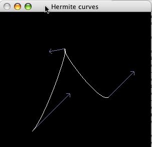
Hermite curves.
Write an openGL program to create two joined Hermite curves that are centered in the graphics window. Draw the non-normalized tangent vectors at each end point using a different color than that used to draw the curves. The head of the tangent vector should be clearly marked (a fat point or an arrow should be sufficient - an example screenshot is provided below. Note that the curve is not centered perfectly in the figure because the example application allows the user to move the entire curve based on a left mouse click. You will not be required to support this mouse event.
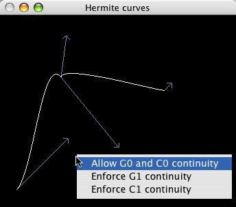
Add a menu to the middle glut button. The menu should support three curve drawing options,
- Allow G0 and C0 continuity (The default for the initial joined curve - the curve is joined but their are no constraints on the tangent vectors. See above figure.)
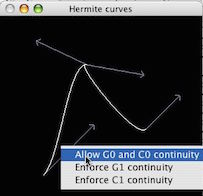
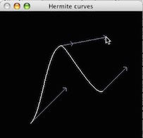
- Enforce G1 continuity (The tangent vectors at a join point
have the same direction. Thus the user can modify any vector's
magnitude but not the direction of the vectors at a join
point. Before and after screenshots are shown below, after the
user has selected "Enforce G1 continuity".)
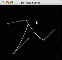
- Enforce C1 continuity (the tangent vectors at a join point have the same direction and magnitude. A screenshot is shown below, after the user has selected "Enforce C1 continuity". Note that only one vector is visible at the join since both vectors have the same direction and magnitude.)
Use the left mouse button (glutMouseFunc callback) to either select a tangent vector for modification or a curve endpoint for modification.
- An endpoint may be dragged to any position within the
window. This will require a redraw of the new curve and should
ensure that the endpoint and tangent vector(s) are moved to
the drag point. The direction and magnitude of the tangent
vector must not change.
- This is tricky - define a small area around the cursor (say 10 pixels) for a distance calculation. On a left mouse click, while button is down, check each endpoint of the curve to determine if it has been selected. If selected then update the curve data and redraw.
- A tangent vector may be dragged to any position within the
window by selecting its head position. This can modify both
the direction and/or the magnitude of the vector.
- Again, pretty tricky - if G0 and C0 continuity are in effect then there are no constraints on how the vector can be modified. If G1 continuity is in effect then the vectors at a join must have the same direction - one vector follows the other's direction but its magnitude does not change. If C1 continuity is in effect then the vectors at a join must have the same direction and magnitude - one vector follows the other's direction and magnitude change.
- If C1 continuity is in effect then the vectors at a joint point will have the same visual representation - only one vector is visible. In this case, your program may simply choose one of the two vectors as the user's selection.
- On a left mouse click, while button is down, check the head of each tangent vector to determine if it has been selected. If selected then update the curve data and redraw.
- The code to define and draw a single Hermite curve is provided below (drawing of tangents vectors is ommitted). No credit will be given for just regurgitating the given code. It is suggested that you use an orthographic projection (below uses perspective) and omit the gluLookAt for the camera position.
-
#include <stdlib.h>
#include <GL/glut.h>
float Geometry[4][3] = {
{ 10,10,0 }, // Point1
{-10,5,-2 }, // Point2
{ 5,-5,0 }, // Tangent1
{ 5,10,0 } // Tangent2
};
int LOD=20;
//----------------------------------------------- OnReshape()
//
void reshape(int w, int h)
{
// prevent a division by zero when minimised
if (h==0)
h=1;
// set the drawable region of the window
glViewport(0,0,w,h);
// set up the projection matrix
glMatrixMode(GL_PROJECTION);
glLoadIdentity();
// just use a perspective projection
gluPerspective(45,(float)w/h,0.1,100);
// go back to modelview matrix so we can move the objects about
glMatrixMode(GL_MODELVIEW);
glLoadIdentity();
}
//------------------------------------------------------- Draw()
//
void display() {
// clear the screen & depth buffer
glClear(GL_COLOR_BUFFER_BIT);
// clear the previous transform
glLoadIdentity();
// set the camera position
gluLookAt( 1,10,30, // eye pos
0,5,0, // aim point
0,1,0); // up direction
glColor3f(0.5,0.5,1);
glBegin(GL_LINE_STRIP);
// use the parametric time value 0 to 1
for(int i=0;i!=LOD;++i) {
float t = (float)i/(LOD-1);
// calculate blending functions
float b0 = 2*t*t*t - 3*t*t + 1;
float b1 = -2*t*t*t + 3*t*t;
float b2 = t*t*t - 2*t*t + t;
float b3 = t*t*t - t*t;
// calculate the x,y and z of the curve point
float x = b0*Geometry[0][0] +
b1*Geometry[1][0] +
b2*Geometry[2][0] +
b3*Geometry[3][0] ;
float y = b0*Geometry[0][1] +
b1*Geometry[1][1] +
b2*Geometry[2][1] +
b3*Geometry[3][1] ;
float z = b0*Geometry[0][2] +
b1*Geometry[1][2] +
b2*Geometry[2][2] +
b3*Geometry[3][2] ;
// specify the point
glVertex3f( x,y,z );
}
glEnd();
glFlush();
}
The following code segment is a template for handling either endpoint or tangent vector modifications.
void click(int button, int state, int x, int y){
     if(button == GLUT_LEFT_BUTTON && state == GLUT_DOWN)
// Find existing point to drag
	 {int minDist = 10;
// Look for closest point within certain tolerance.
	for(int i = 0; i < points; i++)
    //..........
        }
}
Handin - printout the first page of your source code (for my comments and grade assignment) and drop lab folder (source code only!) on moodle. Your folder must be named exactly as CS300Lab6YourName, where you supply your own name for "YourName".
![]()