chapter 1
1.0-1.1 What is computer graphics (CG)?
CG is concerned with all aspects of producing pictures or images using a computer.
- Hardware
- Software
- Applications
CG might be categorized into four broad areas?
Read section 1.1 on your own - simple classification of graphics uses and application types.
1.2 CG Hardware
A graphics system minimally consists of a
processor,
memory,
frame buffer,
output devices, and
input devices.
If we are fortunate the system also contains a high-speed
graphics acceleration card that supports openGL or some other
standard
1.2.1 Frame Buffer (refresh buffer, image buffer, raster)
The frame buffer stores the image to be displayed.
A frame buffer can be visualized as a matrix of picture elements
(pixels) where each pixel is a 1X1 entry.
The frame buffer is stored in memory - in RAM if no special
purpose memory is available or in VRAM (video RAM) or DRAM
(dynamic RAM) - both for high-speed access.
A row of pixels in the buffer is a raster line or scanline.
The size of the buffer (640X480, 1024X1024, etc.) determines the
resolution of the displayed image.
The depth of the buffer (number of bits per pixel) determines
the number of colors that can be displayed.
Examples -
A 1-bit picture element can only display black/white images.
A 2-bit element can display shades of gray.
An 8-bit element can display 256 colors.
A True Color or RGB display contains 24 bits (8 each for red,
green and blue) generating most colors visible to the human eye
(16 million colors). An additional 8-bits may be available to
support transparency.
Buffers currently range up to 96 bits per pixel. Bitmap really
refers to one bit per pixel systems, pixmap to multi-bit
systems, and frame buffer to the actual buffer memory.
1.2.2 CRT (cathode ray tube) Output Device
Prior to 1950's, simple hard copy devices such as line printers were available as graphic output displays.
- CRT (cathode ray tubes) output displays developed in 1950's,
first at M.I.T. Displays contents of frame buffer in "raster mode".
At each pixel (in color systems) three electron guns generate three beams (red, green, blue) whose intensity is based on the value stored in a pixel. The beams are targeted to a small area of the CRT using a "shadow mask" (a film with very small holes). The beams excite the electrons on the phosphor coating - generating a color on the display.
Flat panel displays have a different technology but are still updated in raster mode.
A Brief History of CG
Computer Graphics: 1950-1960
Computer graphics goes back to the earliest days of computing.
- Strip charts
- Pen plotters
- Simple displays using A/D converters to go from computer to calligraphic CRT.
- Computers slow, expensive, unreliable
Computer Graphics: 1960-1970
Wireframe graphics
- Draw only lines
Project Sketchpad
- Ivan Sutherland’s PhD thesis at MIT
- Recognized the potential of man-machine interaction
- Loop
- Display something
- User moves light pen
- Computer generates new display
- Sutherland also created many of the now common algorithms for computer graphics
Display Processors
- Rather than have host computer try to refresh display use a special purpose computer called a display processor (DPU)
- Graphics stored in display list (display file) on display processor
- Host compiles display list and sends to DPU
Direct View Storage tube
- Created by Tektronix
- Did not require constant refresh
- Standard interface to computers
- Allowed for standard software
- Plot3D in Fortran
- Relatively inexpensive
- Opened door to use of computer graphics for CAD community
Computer Graphics: 1970-1980
Raster Graphics
Image produced as an array (the raster) of picture elements (pixels) in the frame buffer.
Allows us to go from lines and wire frame images to filled polygons.
- Inexpensive
- Easy to create filled/patterned polygons
- Refresh rate is independent of the number of polygons in image - same set of pixels are scanned
- Discrete nature of pixel representation implies that polygons (specified as endpoints) are displayed in raster mode.
Raster Mode: Polygons are scan converted to their pixel representation [The image is scanned sequentially from top to bottom and then back to the top again - or the scan can be interlaced (odd scan lines done first, followed by even scan lines - TV technology)].
- Computationally expensive
- Special purpose hardware to perform the scan conversion.
- Continuous functions are approximated leading to aliasing artifacts - jagged look to straight or curved lines.
- Much research has been applied to anti-aliasing techniques to generate more realistic images.
Beginning of graphics standards
- IFIPS
- GKS: European effort becomes ISO 2D standard
- Core: North American effort 3D but fails to become ISO standard
Workstations and PCs
- Although we no longer make the distinction between
workstations and PCs, historically they evolved from different
roots.
- Early workstations characterized by
- Networked connection: client-server model
- High-level of interactivity
- Early PCs included frame buffer as part of user memory
- Easy to change contents and create images
- Early workstations characterized by
Computer Graphics: 1980-1990
Realism comes to computer graphics
|
Smooth Shading
|
Environmental Mapping
|
Bump Mapping
|
- Special purpose hardware
- Silicon Graphics geometry engine
- VLSI implementation of graphics pipeline
- Silicon Graphics geometry engine
- Industry-based standards
- PHIGS
- RenderMan
- Networked graphics: X Window System
- Human-Computer Interface (HCI)
Computer Graphics: 1990-2000
- OpenGL API
- Completely computer-generated feature-length movies (Toy
Story) are successful
- New hardware capabilities
- Texture mapping
- Blending
- Accumulation, stencil buffers
- Texture mapping
- Blending
- Accumulation, stencil buffers
Computer Graphics: 2000-
- Photorealism
- Graphics cards for PCs dominate market
- Nvidia, ATI, 3DLabs
- Game boxes and game players determine direction of market
- Computer graphics routine in movie industry: Maya, Lightwave
1.3 Image Formation
What elements are necessary for image formation (i.e. photography)?
The process of combining the 3D specification of an object (object space) with the 3D specification of a viewer - (world space) - to produce a 2D image (screen or image space) is the essence of CG image formation.
object space --> world space--> image space
1.3.2 Light and Images
An object is only visible if a light source is present.
Light from the source strikes the visible surfaces of an object and is reflected to the camera or the eye.
The interaction of light with the physical or material properties of the object determines the amount of light reflected back to the viewer.
Highly reflective objects such as mirrors reflect almost all light back to the viewer while matte objects (zinc, lead, wood) reflect little light back to the viewer.
Light is an electromagnetic radiation that travels in waves. The visible spectrum of electromagnetic radiation has wavelengths in the range 350-780 nm.
A light source has a color determined by the energy it emits at various wavelengths (blue-lower, green-middle, red-upper: in visible range).
In graphics we rarely deal with the physics of light as a wave - too computationally intensive, instead light is modeled via geometric optics:
This model views light sources as emitters of energy with a fixed intensity.
Light travels in straight lines from source to object.
Point light source (the sun) emits light equally in all directions.
A directional light source (light bulb) emits light over an area and more light in one direction than another.
A light source is characterized by its position, its color (intensity of various wavelengths), and its type: point or directional.
1.3.3 Modeling Light/Object Interaction - Ray Tracing
We can begin thinking about object/light source interaction as follows:
- Given a single point light source that generates infinite rays of light that follow a straight path where the rays emanate in all directions from the source as follows:
Rays A -F in the above diagram demonstrate some of the ways a light ray may interact with an object in the scene:
- ray A intersects no object and enters the lens of the camera (or hits the eye of the viewer).
- ray B leaves the scene.
- ray C intersects a reflective 2-D polygon (on a 3-D object) and generates a reflected ray to the lens.
- ray D intersects a diffuse surface and generates an infinite number of rays in all directions.
- ray E intersects a reflective semi-transparent object generating a reflected ray to the lens and a refracted ray that leaves the scene.
- ray F intersects a reflective 2-D polygon (on a 3-D object) and generates a reflected ray that intersects an absorbing surface.
Ray Tracing is based on this model. This technique simulates complex physical effects at a computational cost. The ray tracing algorithm is covered later in the semester.
In practice, for real-time image formation, a more tractable model is needed. Such illumination models are discussed at length later in the semester.
1.4 Luminance and Color Images
- Luminance Image
- Monochromatic
- Values are gray levels
- Analogous to working with black and white film or television
- Color Image
- Has perceptional attributes of hue, saturation, and lightness
- Do we have to match every frequency in visible spectrum? No!<
Three-Color Theory
 Human visual system has two types of
sensors
Human visual system has two types of
sensors
- Rods: monochromatic, night vision
- Cones
- Color sensitive
- Three types of cones
- Only three values
- Need only match these three values
- Need only three primary colors
Additive and Subtractive Color
- Additive color
- Form a color by adding amounts of three primaries
- CRTs, projection systems, positive film
- Primaries are Red (R), Green (G), Blue (B)
- Form a color by adding amounts of three primaries
- Subtractive color
- Form a color by filtering white light with cyan (C),
Magenta (M), and Yellow (Y) filters
- Light-material interactions
- Printing Negative film
- Form a color by filtering white light with cyan (C),
Magenta (M), and Yellow (Y) filters
1.5 Pinhole Camera
A pinhole camera is a box with a small hole in one side and a film placed opposite the hole and inside the box. Assume the camera is oriented along the z-axis with the pinhole at the origin of our coordinate system. Only a single ray of light may enter the pinhole.
Here we see a ray originating from point (x, y, z) and striking the film of the camera at point (xp, yp, zp) a distance d from the origin. The film plane is thus at z = -d.
How do we calculate the projection of (x, y, z) to (xp, yp, zp)?
The field or angle of view of the camera is the angle made by the largest object the camera can image on its film plane. The pinhole camera has a very limited field of view.
A more sophisticated camera with a lens can collect more light and the focal length of the lens can allow an angle of view up to 180 degrees.
The ideal pinhole camera has an infinite depth of field (every point is in focus). Lenses on the other hand do not have an infinite depth of field.
For simplicity we assume an infinite depth of field for CG scenes. Later we will discuss techniques to determine whether objects are in focus or not.
1.6 Synthetic Camera Model (Camera basics)
In computer graphics, image generation is modeled on the process of image formation using an optical system - thus the term synthetic camera.
The specification of objects is independent of the viewer or camera.
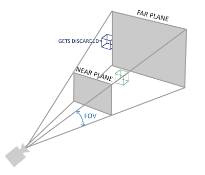
The camera is given a position called the center of projection (COP) and a lens orientation. The camera's angle of view is specified.
The image is computed using calculations similar to those demonstrated in the pinhole camera example. This is done by moving the film plane of the camera in front of the camera lens. The moved film plane is called the projection or image plane. The image is projected onto the projection plane. Field of view is handled by placing a clipping rectangle around the projection plane so that objects outside the field of view are clipped from the scene.
Advantages
- Separation of objects, viewer, light sources
- Two-dimensional graphics is a special case of three-dimensional graphics
- Leads to simple software API
- Specify objects, lights, camera, attributes
- Let implementation determine image
Global vs Local Lighting
- Cannot compute color or shade of each object independently
- Some objects are blocked from light
- Light can reflect from object to object
- Some objects might be translucen
Why not RayTracing?
- Ray tracing seems more physically based so why don’t we use it to design a graphics system?
- Possible and is actually simple for simple objects such as polygons and quadrics with simple point sources
- In principle, can produce global lighting effects such as shadows and multiple reflections but ray tracing is slow and not well-suited for interactive applications
1.7 Models and Architectures
- Objectives
- Learn the basic design of a graphics system
- Introduce pipeline architecture
- Examine software components for an interactive graphics system
Image Formation Revisited
- Can we mimic the synthetic camera model to design graphics hardware software?
- Application Programmer Interface (API)
- Need only specify
- Objects
- Materials
- Viewer
- Lights
- Need only specify
- But how is the API implemented?
Physical Approaches
- Ray tracing: follow rays of light from center of projection
until they either are absorbed by objects or go off to
infinity
- Can handle global effects
- Multiple reflections
- Translucent objects
- Slow
- Need whole data base
- Radiosity: Energy based approach
- Very slow
- Practical Approach: process objects one at a time in the order they are generated by the application
- Can consider only local lighting
- Pipeline architecture
- All steps can be implemented in hardware on the graphics card
The Programmer’s Interface
- Programmer sees the graphics system through a software interface: the Application Programmer Interface (API)
API Contents
- Functions that specify what we need to form an image
- Objects
- Viewer
- Light Source(s)
- Materials
- Other information
- Input from devices such as mouse and keyboard
- Capabilities of system
Object Specification
- Most APIs support a limited set of primitives including
- Points (1D object)
- Line segments (2D objects)
- Polygons (3D objects)
- Some curves and surfaces
- Quadrics
- Parametric polynomials
- All are defined through locations in space or vertices
- Example
glBegin(GL_POLYGON)
glVertex3f(0.0, 0.0, 0.0);
glVertex3f(0.0, 1.0, 0.0);
glVertex3f(0.0, 0.0, 1.0);
glEnd( );
Camera Specification
- Six degrees of freedom
- Position of center of lens (COP - center of projection, VRP - Angel's view-reference point)
- Orientation (EULER transforms - up, pitch and yaw
- Lens
- Film size
- Orientation of film plane
Lights and Materials
- Types of lights
- Point sources vs distributed sources
- Spot lights
- Near and far sources
- Color properties
- Material properties
- Absorption: color properties
- Scattering
- Diffuse
- Specular
Following the Pipeline: Transformations
- Much of the work in the pipeline is in converting object
representations from one coordinate system to another
- Object or model coordinates
- Camera or world coordinates
- Screen coordinates
- Every change of coordinates is equivalent to a matrix transformation
Clipping
- Just as a real camera cannot “see” the whole world, the
virtual camera can only see part of the world space
- Objects that are not within this volume are said to be
clipped out of the scene
- Objects that are not within this volume are said to be
clipped out of the scene
Projection
- Must carry out the process that combines the 3D viewer with
the 3D objects to produce the 2D image
- Perspective projections: all projectors meet at the center of projection
- Parallel projection: projectors are parallel, center of projection is replaced by a direction of projection
Rasterization
- If an object is visible in the image, the appropriate pixels
in the frame buffer must be assigned colors
- Vertices assembled into objects
- Effects of lights and materials must be determined
- Polygons filled with interior colors/shades
- Must also determine which objects are in front (hidden surface removal)
Questions and Answers
How was this image produced?
Preliminary Answer
- Application: The object is an artist’s rendition of the sun for an animation to be shown in a domed environment (planetarium)
- Software: Maya for modeling and rendering but Maya is built on top of OpenGL
- Hardware: PC with graphics card for modeling and rendering
Four areas of CG
- display of information
- design
- simulation and animation
- user interfaces.
-Application programs have replaced textual manipulation with graphic-based interaction (gui's)
-2D and 3D graphics are common place
-The division between computer graphics and image processing has become blurred
-The ability to graphically view large and complicated data sets: (MRI, PET, VLSI, CAD/CAM)
-Static and animated viewing is possible
-Visualization of abstract "objects" that have no defined geometry
-Learning, training, and entertainment through simulations and virtual environments : (Flight Simulators)
-"Pretty" pictures
-Etc.
Image formation
We live in a world of 3D objects - we think about the reference points on an object, distances between objects, etc. which are specified in some convenient coordinate system.
We use mathematics such as geometry and trig to measure size and distance.
We use physical devices such as cameras, microscopes, telescopes, and our eyes to understand spatial relationships between objects.
There is a fundamental link between the physics and mathematics of image formation in computer graphics.
Necessary elements
- Objects - defined in 3D object or model space
- Viewer (camera) -defined in 3D world space
- Light - defined in world space
- Material properties - how light interacts with objects
- Object, viewer, light are independent
Projection of point
Note the similar triangles created by (0, 0, 0), (0, 0, z), (0, y, z) and (0, 0, 0), (0, 0, -d), (0, yp, -d). Both are right triangles with equal angles at the origin.
Using the fact that the ratio of two legs of similar triangles are equal we note that
x/z = xp/-d and
y/z = yp/-d
Then solving for xp, yp we find
xp = -x/(z/d)
yp = -y/(z/d)
zp = -d
The point (xp, yp, -d) is a projection of the point (x, y, z) - discussed in depth later in the semester.