chapter 4.3
- Learn how to carry out transformations
in
OpenGL
- Rotation
- Translation
- Scaling
- Introduce OpenGL matrix modes
- Model-view
- Projection
OpenGL Matrices
- In OpenGL matrices are part of the state
- Three types
- Model-View (GL_MODEL_VIEW)
- Projection (GL_PROJECTION)
- Texture (GL_TEXTURE) (ignore for now)
- Single set of functions for manipulation
- Select which to manipulated by
- glMatrixMode(GL_MODEL_VIEW);
- glMatrixMode(GL_PROJECTION);
Current Transformation Matrix (CTM)
- Conceptually there is a 4 x 4 homogeneous coordinate matrix, the current transformation matrix (CTM) that is part of the state and is applied to all vertices that pass down the pipeline
- The CTM is defined in the user program and loaded into a transformation unit

CTM operations
- The CTM can be altered either by
loading a
new CTM or by post-mutiplication
- Load an identity matrix: C
 I
I
Load an arbitrary matrix: C M
M
Load a translation matrix: C T
T
Load a rotation matrix: C R
R
Load a scaling matrix: C S
S
Postmultiply by an arbitrary matrix: C CM
CM
Postmultiply by a translation matrix: C CT
CT
Postmultiply by a rotation matrix: C C R
C R
Postmultiply by a scaling matrix: C C S
C S
- Load an identity matrix: C
Rotation about a Fixed Point
- Start with identity matrix: C
 I
I - Move fixed point to origin: C
 CT -1
CT -1 - Rotate: C
 CR
CR - Move fixed point back: C
 CT
CT - Result: C = T RT-1
- Each operation corresponds to one function call in the program.
- Note that the last operation specified is the first executed in the program
CTM in OpenGL
- OpenGL has a model-view and a projection matrix in the pipeline which are concatenated together to form the CTM
- Can manipulate each by first setting the correct matrix mode

Rotation, Translation, Scaling
(see code model.c )- Load an identity matrix:
- glLoadIdentity()
- Multiply on right:
- glRotatef(theta, vx, vy, vz)
- theta in degrees, (vx, vy, vz) define axis of rotation
- glTranslatef(dx, dy, dz)
- glScalef( sx, sy, sz)
- glRotatef(theta, vx, vy, vz)
- Each has a float (f) and double (d) format (glScaled)
Example
- Rotation about z axis by 30 degrees
with a
fixed point of (1.0, 2.0, 3.0)
glMatrixMode(GL_MODELVIEW);
glLoadIdentity();
glTranslatef(1.0, 2.0, 3.0);
glRotatef(30.0, 0.0, 0.0, 1.0);
glTranslatef(-1.0, -2.0, -3.0); - Remember that last matrix specified in the program is the first applied
Arbitrary Matrices
- Can load and multiply by matrices defined in the application program
- The matrix m is a one dimension array of 16 elements which are the components of the desired 4 x 4 matrix stored by columns
- In glMultMatrixf, m multiplies the existing matrix on the right
glLoadMatrixf(m)
glMultMatrixf(m)
Matrix Stacks
- In many situations we want to save
transformation matrices for use later
- Traversing hierarchical data structures
- Avoiding state changes when executing display lists
- OpenGL maintains stacks for each type
of
matrix
- Access current stack type (as set
by
glMatrixMode) with
- glPushMatrix()
glPopMatrix()
- glPushMatrix()
- Access current stack type (as set
by
glMatrixMode) with
Reading Back Matrices
- Can also access matrices (and other parts of the state) by enquiry (query) functions
- For matrices, we use
double m[16];
glGetFloatv(GL_MODELVIEW, m);
glGetIntegerv
glGetFloatv
glGetBooleanv
glGetDoublev
glIsEnabled
Using Transformations
- Example: use idle function to rotate a cube and mouse function to change direction of rotation
- Start with a program that draws a cube
(cube.c)
in
a standard way
- Centered at origin
- Sides aligned with axes
//main.c

            void main(int argc, char **argv)

            {
              glutInit(&argc, argv);

              glutInitDisplayMode(GLUT_DOUBLE | GLUT_RGB |

              GLUT_DEPTH);

              glutInitWindowSize(500, 500);

              glutCreateWindow("colorcube");

              glutReshapeFunc(myReshape);

              glutDisplayFunc(display);

              glutIdleFunc(spinCube);

              glutMouseFunc(mouse);

              glEnable(GL_DEPTH_TEST);
              glutMainLoop();

              }
            //Idle and Mouse callbacks

            void spinCube()

            {
              theta[axis] += 0.05;

              if( theta[axis] > 360.0 ) theta[axis] -= 360.0;

              glutPostRedisplay();

              }
void mouse(int btn, int state, int
            x,
            int y)

            {
              if(btn==GLUT_LEFT_BUTTON && state == GLUT_DOWN)

              axis = 0;

              if(btn==GLUT_MIDDLE_BUTTON && state == GLUT_DOWN)


              axis = 1;

              if(btn==GLUT_RIGHT_BUTTON && state == GLUT_DOWN)

              axis = 2;

              }
            //Display callback

            void display()

            {
              glClear(GL_COLOR_BUFFER_BIT | GL_DEPTH_BUFFER_BIT);

              glLoadIdentity();

              glRotatef(theta[0], 1.0, 0.0, 0.0);

              glRotatef(theta[1], 0.0, 1.0, 0.0);

              glRotatef(theta[2], 0.0, 0.0, 1.0);

              colorcube(); //left for later

              glutSwapBuffers();

              }
- Note that because of fixed form of callbacks, variables such as theta and axis must be defined as globals
- Camera information is in standard reshape callback
Using the Model-View Matrix
- In OpenGL the model-view matrix is used
to
- Position the camera
- Can be done by rotations and translations but is often easier to use gluLookAt - later
- Build models of objects
- Position the camera
- The projection matrix is used to define the view volume and to select a camera lens
- Although both are manipulated by the
same
functions, we have to be careful because incremental changes
are always
made by postmultiplication
- For example, rotating model-view and projection matrices by the same matrix are not equivalent operations. Postmultiplication of the model-view matrix is equivalent to premultiplication of the projection matrix
Smooth Rotation
- From a practical standpoint, we often
want
to use transformations to move and reorient an object
smoothly
- Problem: find a sequence of model-view matrices M0,M1, &..,Mn so that when they are applied successively to one or more objects we see a smooth transition
- For orientating an object, we can use
the
fact that every rotation corresponds to part of a great
circle on a
sphere
- Find the axis of rotation and angle
- Virtual trackball (see text and trackball.rtf)
Incremental Rotation
- Consider the two approaches
- For a sequence of rotation matrices
R0,
R1, &.., Rn , find the Euler
angles for each
and use Ri= Riz Riy Rix
- Not very efficient
- Use the final positions to determine the axis and angle of rotation, then increment only the angle
- For a sequence of rotation matrices
R0,
R1, &.., Rn , find the Euler
angles for each
and use Ri= Riz Riy Rix
- Quaternions can be more efficient than
either - advanced topic not addressed
- Quaternions do NOT suffer from "gimbol lock" as do Euler Angles. Gimbol lock occurs with rotations of 90 degrees - one coordinate axis is collapsed onto another - and further rotations around the collasped axis cannot occur.
Interfaces
- One of the major problems in interactive computer graphics is how to use two-dimensional devices such as a mouse to interface with three dimensional objects
- Example: how to form an instance matrix?
- Some alternatives
- Virtual trackball
- 3D input devices such as the spaceball
- Use areas of the screen
- Distance from center controls angle, position, scale depending on mouse button depressed
Building Models
Objectives
- Introduce simple data structures for
building polygonal models
- Vertex lists
- Edge lists
- OpenGL vertex arrays
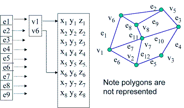
Representing a Mesh
- Consider a mesh
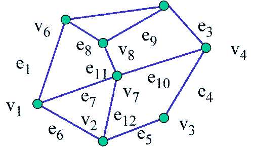
- There are 8 nodes and 12 edges
- 5 interior polygons
- 6 interior (shared) edges
- Each vertex has a location vi = (xi yi zi)
Simple Representation
- Define each polygon by the geometric locations of its vertices
- Leads to OpenGL code such as
- Inefficient and unstructured
- Consider moving a vertex to a new location
glBegin(GL_POLYGON);

                glVertex3f(x1, y1, z1);

                glVertex3f(x2, y2, z2);

                glVertex3f(x7, y7, z7);

                glEnd();
Inward and Outward Facing Polygons
- The order {v1, v0, v3, v2} and {v2, v1, v0, v3} are equivalent in that the same polygon will be rendered by OpenGL but the order {v1, v2, v3, v0} is different (the first is counter-clockwise, the second is clockwise)
- The first two describe outwardly facing
polygons
-
Use the right-hand rule =
counter-clockwise encirclement
of outward-pointing normal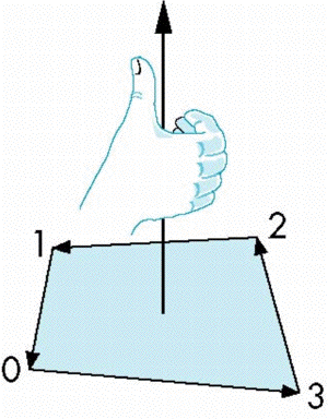
-
- OpenGL can treat inward and
outward facing polygons differently
Geometry vs Topology
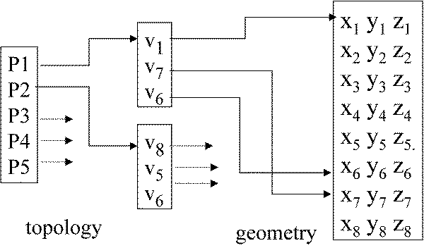
- Generally it is a good idea to look for
data structures that separate the geometry from the topology
- Geometry: locations of the vertices
- Topology: organization of the vertices and edges
- Example: a polygon is an ordered list of vertices with an edge connecting successive pairs of vertices and the last to the first
- Topology holds even if geometry changes
Vertex Lists
- Put the geometry in an array
- Use pointers from the vertices into this array
- Introduce a polygon list
Shared Edges
- Vertex lists will draw filled polygons correctly but if we draw the polygon by its edges, shared edges are drawn twice
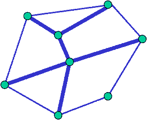
- Can store mesh by edge list
Edge List
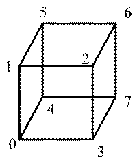
Modeling a Cube (as in cube.c)
- Model a color cube for rotating cube program
- Define global arrays for vertices and
colors
GLfloat vertices[][3] =
                  {{-1.0,-1.0,-1.0},{1.0,-1.0,-1.0},

                  {1.0,1.0,-1.0}, {-1.0,1.0,-1.0}, {-1.0,-1.0,1.0},

                  {1.0,-1.0,1.0}, {1.0,1.0,1.0}, {-1.0,1.0,1.0}};
GLfloat colors[][3] = {{0.0,0.0,0.0},{1.0,0.0,0.0},
{1.0,1.0,0.0}, {0.0,1.0,0.0}, {0.0,0.0,1.0},
{1.0,0.0,1.0}, {1.0,1.0,1.0}, {0.0,1.0,1.0}};
Drawing a polygon from a
list
of indices
- Draw a quadrilateral from a list of
indices into the array vertices and use color corresponding
to first
index
void polygon(int a, int b, int c
                ,
                int d){
glBegin(GL_POLYGON);
glColor3fv(colors[a]);
glVertex3fv(vertices[a]);
glVertex3fv(vertices[b]);
glVertex3fv(vertices[c]);
glVertex3fv(vertices[d]);
glEnd();
}
//Draw cube from faces

                void colorcube( ){
                  polygon(0,3,2,1);

                  polygon(2,3,7,6);

                  polygon(0,4,7,3);

                  polygon(1,2,6,5);

                  polygon(4,5,6,7);

                  polygon(0,1,5,4);

} - Note that vertices are ordered so that
we
obtain correct outward facing normals
Efficiency
- The weakness of our approach is that we are building the model in the application and must do many function calls to draw the cube
- Drawing a cube by its faces in the most
straight forward way requires
- 6 glBegin, 6 glEnd
- 6 glColor
- 24 glVertex
- More if we use texture and lighting
Vertex Arrays
- OpenGL provides a facility called vertex arrays that allows us to store array data in the implementation
- Six types of arrays supported
- Vertices
- Colors
- Color indices
- Normals
- Texture coordinates
- Edge flags
- We will need only colors and vertices
Initialization
- Using the same color and vertex data,
first we enable
glEnableClientState(GL_COLOR_ARRAY);glEnableClientState(GL_VERTEX_ARRAY); - Identify location of arrays
glVertexPointer(3, GL_FLOAT,
                  0,
                  vertices);
glColorPointer(3, GL_FLOAT, 0, colors);
Mapping indices to faces
- Form an array of face indices
- Each successive four indices describe a face of the cube
- Draw through glDrawElements which replaces all glVertex and glColor calls in the display callback
GLubyte cubeIndices[24] =
                {0,3,2,1,2,3,7,6

                0,4,7,3,1,2,6,5,4,5,6,7,0,1,5,4};
Drawing the cube
- Method 1:


- One function call